Stepper motor working principle and use instructions
1.Introduction
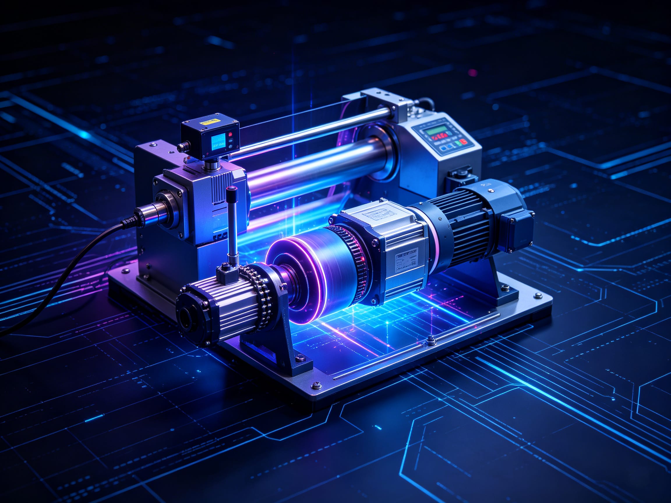
Stepper motor is an open-loop control element that converts the electrical pulse signal into angular displacement or linear displacement. In the case of non-overload, the speed of the motor and the stopping position depend only on the frequency and number of pulses of the pulse signal, and are not affected by load changes, that is, to add a pulse signal to the motor, the motor turns a step Angle. The existence of this linear relationship, coupled with the stepper motor only periodic error without cumulative error and so on. It makes it very simple to control with stepper motor in speed, position and other control fields.
Although the stepper motor has been widely used, the stepper motor can not be used as an ordinary DC motor, and the AC motor is used in a conventional manner. It must be composed of double ring pulse signal, power drive circuit and other control system can be used. Therefore, it is not easy to use a good stepper motor, which involves many professional knowledge such as machinery, motors, electronics and computers. At present, the production of stepper motor manufacturers is indeed a lot, but with professional and technical personnel, can develop themselves, the development of manufacturers is very few, most of the manufacturers only one or twenty people, even the most basic equipment is not available. It's just a kind of blind imitation. This causes a lot of trouble for users in product selection and use. In light of the above, we decided to take a wide range of inductor stepper motors as an example. The basic working principle is described. Hope to be helpful to the majority of users in the selection, use, and improvement of the whole machine.
2.the working principle of induction stepper motor
1. Structure:
The rotor of the motor is evenly distributed with many small teeth, and the stator teeth have three exciting winding, and the geometric axis is staggered with the rotor tooth axis in turn. 0, 1/3て, 2/3て, (the distance between the axes of the adjacent two rotors is the tooth pitch expressed by て), that is, A is aligned with tooth 1, B is staggered to the right by 1/3て, C is staggered to the right by tooth 3 by 2/3て, A' is aligned with tooth 5, (A' is A, tooth 5 is tooth 1)
2. Rotation:
If A is connected to electricity, B, C phase is not energized, due to the magnetic field, tooth 1 is aligned with A, (the rotor is not subject to any force).
If B is connected with electricity and A and C are not powered on, tooth 2 should be aligned with B. At this time, the rotor moves to the right by 1/3て, the offset between tooth 3 and C is 1/3て, and the offset between tooth 4 and A is (て-1/3て) =2/3て.
If C is connected to electricity and A and B are not powered on, tooth 3 should be aligned with C. At this time, the rotor is moved to the right 1/3て, and tooth 4 is aligned with A 1/3 offset て.
If A is connected to electricity, B, C phase is not powered on, tooth 4 is aligned with A, and the rotor is moved to the right 1/3て
In this way, after A, B, C and A are energized respectively, tooth 4 (that is, the first tooth of tooth 1) moves to phase A, the motor rotor turns A tooth pitch to the right, if the press A, B, C, A...... continuously Power on, the motor on each step (each pulse) 1/3て, rotation to the right. Press A, C, B, A...... Power on, the motor reverses.
It can be seen that the position and speed of the motor are one-to-one corresponding to the number of conduction times (pulse number) and frequency. The direction is determined by the conduction sequence.
However, due to the consideration of torque, stability, noise and reduction Angle. The conductive state of A-AB-B-BC-C-CA-A is often used, so that the original 1/3て is changed to 1/6て at each step. Even through the different combination of two-phase current, the 1/3て becomes 1/12て, 1/24て, which is the basic theoretical basis of motor subdivision drive.
It is not difficult to conclude that there is m phase excitation winding on the motor stator, and its axis is offset by 1/m and 2/m...... respectively (m minus 1)/m,1. And conduction according to a certain phase sequence of the motor can be controlled positive and negative rotation - this is the physical condition of the stepper motor rotation. As long as this condition is met, we can theoretically manufacture any phase of the stepper motor, due to cost and other considerations, the market is generally two, three, four, five phases.
3. Torque:
Once the motor is energized, a magnetic field (magnetic flux) will be generated between the fixed rotor when the rotor and the stator stagger a certain Angle to produce force
F is proportional to (d diameter /dθ) S
Its magnetic flux diameter =Br*S
Br is magnetic density and S is magnetic permeability area
F is proportional to L*D*Br
L is the effective length of the iron core and D is the diameter of the rotor
Br=N•I/R
N•I is the ampere-turns of excitation winding (current multiplied by turns) and R is the magnetoresistance.
Torque = force * radius
The torque is proportional to the effective volume * ampere-turns * magnetic density of the motor (only linear state is considered)
Therefore, the larger the effective volume of the motor, the larger the field ampere-turns, the smaller the air gap between the fixed rotor, the greater the motor torque, and vice versa.