Common EtherCAT Integrated Motor Setup Issues and How to Fix Them
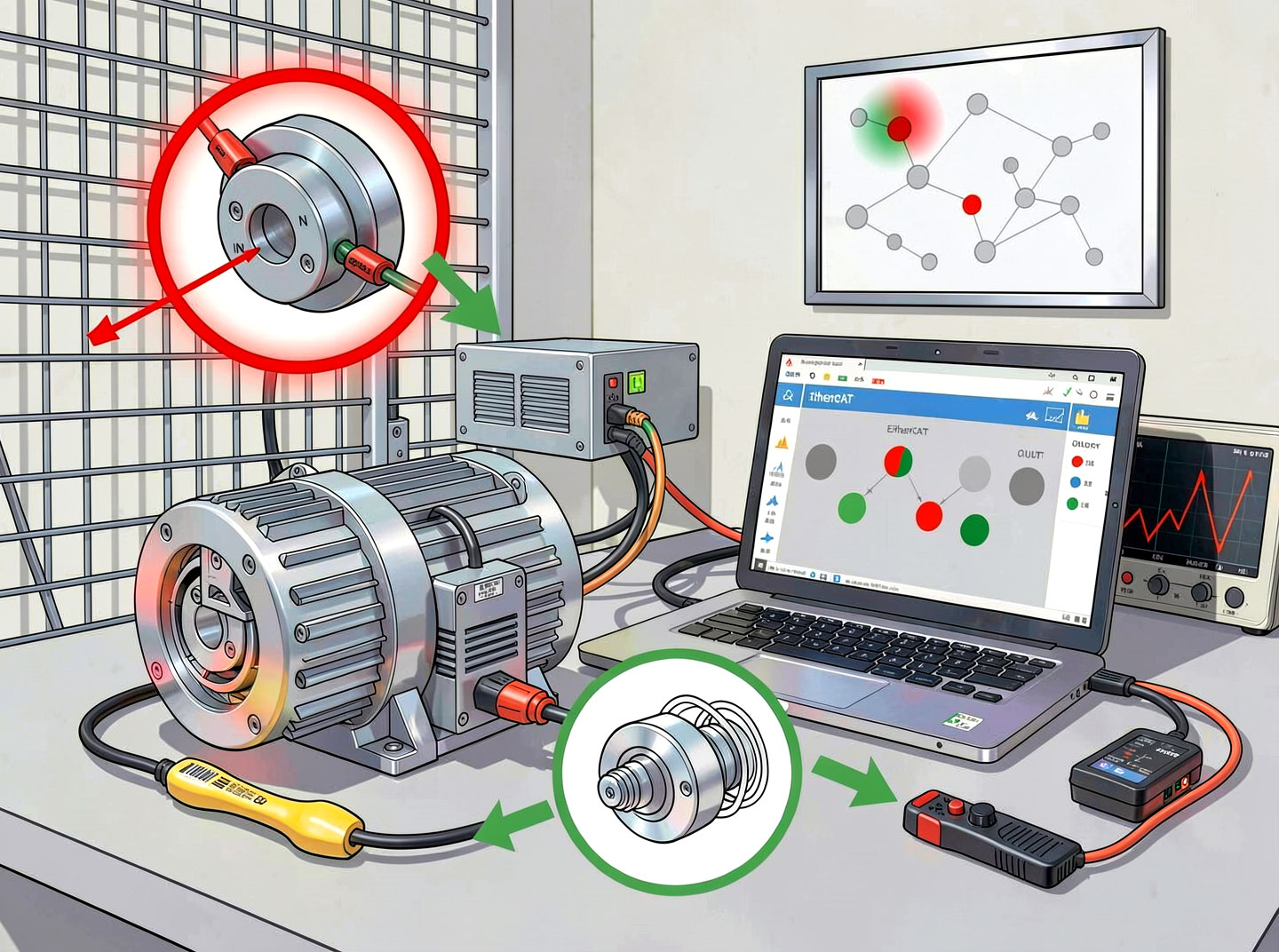
The EtherCAT Integrated Motor combines a servo motor, drive, and real‑time communication into a single compact device. While this integration simplifies wiring and reduces cabinet space, it also introduces new challenges during setup and commissioning. Unlike traditional systems where the drive and motor are separate, an integrated motor’s electronics are exposed to motor heat, vibration, and electromagnetic interference from the very cables that power it. Moreover, the EtherCAT communication stack must be correctly configured – from PDO mapping and distributed clocks to state machine transitions and CiA 402 profile settings.

This article, exceeding 15,000 words, provides a comprehensive guide to the most common setup issues encountered with EtherCAT Integrated Motor systems. For each problem, we describe the symptoms, root causes, step‑by‑step troubleshooting procedures, and long‑term preventive measures. We also include real‑world case studies, diagnostic object tables, and a quick reference flowchart. Whether you are a system integrator, maintenance engineer, or machine builder, this guide will help you resolve issues quickly and avoid them in future projects.
Part 1: Overview of Typical Setup Issues
Before diving into specific problems, it helps to categorise the types of issues that arise with EtherCAT Integrated Motor installations.
1.1 Categories of Issues
CategoryDescriptionCommon ExamplesCommunicationProblems with EtherCAT frame exchange, state machine, or PDOsNo communication, state stuck in Pre‑Op, PDO mapping errorsSynchronisationIssues related to distributed clocks and timingAxis drift, jitter, following errors, DC driftConfigurationIncorrect parameters in the ESI file or master setupWrong PDO lengths, missing objects, cycle time mismatchElectrical/EMCNoise, grounding, power supply problemsIntermittent errors, frame loss, motor stallsMechanical/thermalOverheating, vibration, mechanical resonanceOver‑temperature shutdown, audible noise, poor torqueFirmware/softwareBugs, version mismatches, incomplete implementationsUnexpected behaviour, failed autotuning, object access errors
1.2 Why Integrated Motors Have Unique Setup Challenges
Heat – The drive electronics are inside the motor housing, so thermal derating is critical.
Vibration – The motor’s own motion can shake loose connectors or damage cables.
EMI – Power and EtherCAT share the same cable bundle (or even the same connector in some hybrid designs), increasing noise coupling.
Limited diagnostics – Without a separate drive panel, there are no LEDs or displays; you rely entirely on EtherCAT objects.
Understanding these factors will help you interpret symptoms correctly.
Part 2: Issue #1 – No EtherCAT Communication (State Machine Stuck in Init)
2.1 Symptoms
The EtherCAT master cannot detect the EtherCAT Integrated Motor at all.
The motor’s status LED (if present) is off or flashing red.
The master’s bus scan shows no slave at the expected position.
2.2 Root Causes
Power supply missing or incorrect voltage – The motor’s logic power (usually 24 V DC) is not present, or the voltage is too low (<18 V) or too high (>30 V).
Cable fault – Broken wire, short circuit, or incorrect wiring (e.g., swapped Tx/Rx pairs).
EtherCAT cable not shielded or too long – Excessive length (>100 m) or poor quality cable.
Termination missing – On a daisy‑chain, the last motor’s OUT port must be left open (or terminated if required). Some masters need a termination resistor on the last slave.
Slave address conflict – Two motors have the same configured address (if using explicit addressing).
Hardware failure – Damaged EtherCAT slave controller (ESC) or power stage.
2.3 Step‑by‑Step Troubleshooting
Step 1: Verify power supply.
Measure voltage at the motor’s power input terminals. It should be within the specified range (e.g., 24 V DC ±10%).
Check if the motor has a separate logic supply (some models). If yes, both power and logic must be present.
Step 2: Check EtherCAT cable and connectors.
Use a cable tester to verify continuity and pinout (EtherCAT uses standard Ethernet pinout: pins 1,2 transmit; 3,6 receive; 4,5 and 7,8 not used for 100BASE‑TX).
Replace the cable with a known good shielded CAT5e or CAT6 cable.
Ensure metal RJ45 connectors are used and the shield is properly connected to ground (at one end only).
Step 3: Inspect the physical topology.
If daisy‑chaining, ensure the master’s OUT goes to the first motor’s IN, then its OUT to the next motor’s IN, etc.
The last motor’s OUT should be empty (no cable). Do not loop back unless using ring redundancy.
Step 4: Test with minimal setup.
Disconnect all motors except one. Connect it directly to the master with a short (1‑2 m) cable. Scan again.
If it works, the problem is in the cabling or another motor. If it still fails, the motor or master port may be faulty.
Step 5: Check slave addressing.
If using explicit addressing (not auto‑increment), verify that no two motors share the same address. Use the master’s “set station address” function.
Step 6: Examine the master’s error log.
Most EtherCAT masters (TwinCAT, Codesys, etc.) provide detailed error messages: “No slave found”, “Invalid vendor ID”, “Link down”. Use these to narrow the cause.
2.4 Preventive Measures
Always use pre‑tested, shielded EtherCAT cables with metal connectors.
Keep cable lengths well below 100 m (recommend ≤50 m for integrated motors due to noise).
Document the topology and verify power sequencing (logic power before motor power).
2.5 Case Example
Scenario: A machine builder could not get any response from a new EtherCAT Integrated Motor on a daisy‑chain of 5 motors. The first motor worked, but the second and beyond were invisible.
Diagnosis: The cable between motor 1 and motor 2 was a standard unshielded Ethernet cable (CAT5 UTP). After replacing it with a shielded CAT6 cable, all motors appeared. The unshielded cable allowed EMI from the motor’s power stage to corrupt the EtherCAT signal.
Part 3: Issue #2 – State Machine Stuck in Pre‑Operational (Pre‑Op) or Safe‑Op
3.1 Symptoms
The master can see the motor (it appears in the bus scan), but the motor’s state does not transition to Operational.
The master shows “Pre‑Operational” or “Safe‑Operational” status.
The motor does not respond to cyclic commands (no movement).
3.2 Root Causes
Missing or incorrect Sync Manager configuration – The master has not configured SM2 (outputs) and SM3 (inputs) correctly.
PDO mapping mismatch – The PDOs defined in the master do not match those in the motor’s ESI file.
Distributed clock (DC) configuration error – The master requests a DC cycle time that the motor does not support.
Watchdog not configured – Some motors require a watchdog timer to be set before entering Operational.
Firmware version mismatch – The ESI file is for a newer firmware than what is on the motor.
3.3 Step‑by‑Step Troubleshooting
Step 1: Check the master’s error message.
Most masters display a specific reason: “Invalid PDO mapping”, “DC sync error”, “SM configuration failed”.
Step 2: Verify the ESI file is correct and loaded.
Download the latest ESI file from the motor vendor’s website. Replace the old one.
Reload the ESI into the master’s device repository.
Step 3: Examine PDO mapping.
In the master’s configuration, go to the “Process Data” tab for the motor.
Ensure the TxPDO (from motor to master) includes at least Statusword (0x6041) and Actual position (0x6064).
Ensure the RxPDO (master to motor) includes Controlword (0x6040) and Target position (0x607A) if using CSP mode.
Check that the PDO lengths match the ESI specification (e.g., 4 bytes for a 32‑bit integer).
Step 4: Test with a minimal PDO mapping.
Remove all optional PDOs. Keep only mandatory objects. If the motor then enters Operational, the issue is an unsupported optional object.
Step 5: Check DC settings.
If DC is enabled, ensure the cycle time (e.g., 1 ms) is supported by the motor. Some motors only support 1 ms, 2 ms, or 4 ms.
Try disabling DC temporarily. If the motor enters Operational with DC off, then DC configuration is the problem.
Step 6: Verify the control word sequence.
Even if the motor is in Operational, it may not be enabled. Check the master’s “Enable” logic. The motor requires the sequence: 0x06 → 0x07 → 0x0F (see CiA 402).
3.4 Preventive Measures
Always use the vendor’s official ESI file; never edit it manually unless you are an expert.
Before production, test the motor with your master using the exact PDO mapping you intend to use.
Keep a log of supported DC cycle times for each motor model.
3.5 Case Example
Scenario: An integrator using Codesys could not get an EtherCAT Integrated Motor to go beyond Safe‑Operational. The master reported “SM2 configuration failed”.
Diagnosis: The motor’s ESI file had a custom PDO that required 6 bytes of output data, but the master’s default PDO assignment only allocated 4 bytes. After manually increasing the output PDO size to 6 bytes, the motor transitioned to Operational.
Part 4: Issue #3 – Random Communication Errors, Frame Loss, or Intermittent Stalls
4.1 Symptoms
The motor runs for a while, then stops unexpectedly.
The master logs “Lost frame”, “CRC error”, or “Slave not responding”.
The motor’s position jumps or vibrates erratically.
4.2 Root Causes
Electromagnetic interference (EMI) – Unshielded cables, poor grounding, or proximity to high‑power inverters.
Cable fatigue – The EtherCAT cable is flexing (e.g., on a robot arm) and has developed intermittent breaks.
Power supply ripple – The DC supply has excessive ripple (>5%) causing the motor’s internal logic to reset.
Overheating – The motor’s internal temperature exceeds the limit, causing the EtherCAT controller to throttle or reset.
Firmware bug – Some early firmware versions have known issues with long‑term stability.
4.3 Step‑by‑Step Troubleshooting
Step 1: Monitor the master’s diagnostic counters.
In TwinCAT, use the “EtherCAT Diagnostics” to view CRC errors, lost frames, and re‑transmissions.
In Codesys, use the EtherCAT master status variables.
Step 2: Isolate the source.
Reduce the system to a single motor with a short, high‑quality shielded cable. If errors disappear, the problem is cabling or EMI.
If errors persist, replace the motor and the master port one at a time.
Step 3: Check grounding and shielding.
Ensure the EtherCAT cable shield is connected to ground at one end only (to avoid ground loops).
Verify that the motor’s PE (protective earth) terminal is connected to a common star ground point.
Keep power cables and EtherCAT cables at least 10 cm apart. Cross at 90° if unavoidable.
Step 4: Examine the power supply.
Use an oscilloscope to measure DC bus voltage ripple. It should be <5% of nominal voltage.
Add a ferrite core on the power input cable (one turn through a ferrite ring) to suppress high‑frequency noise.
Step 5: Check temperature.
Read the motor’s internal temperature via CoE object 0x2020 (vendor‑specific) or 0x2100.
If temperature >85°C, the motor is overheating. Reduce load, improve cooling, or derate torque.
Step 6: Update firmware.
Contact the vendor for the latest firmware. Update via FoE (File over EtherCAT).
4.4 Preventive Measures
Use CAT6 S/FTP (shielded, foil + braid) cables for all EtherCAT connections.
Install ferrite cores on power cables for every motor.
Perform a thermal analysis to ensure adequate cooling for all integrated motors.
Regularly check diagnostic counters; an increasing CRC error rate predicts cable failure.
4.5 Case Example
Scenario: A packaging machine with 8 integrated motors would randomly lose communication with one motor once every few hours. The master showed “CRC error” on that specific slave.
Diagnosis: The cable from the previous motor to the problematic one passed near a 10 kW variable frequency drive (VFD). The VFD’s radiated EMI corrupted the EtherCAT signal. After rerouting the cable 30 cm away and adding a ferrite core, the errors stopped.
Part 5: Issue #4 – Position Drift or Loss of Synchronisation (Distributed Clock Issues)
5.1 Symptoms
Multiple EtherCAT Integrated Motor axes that should move together gradually lose alignment over time.
After several minutes or hours, the end effector is no longer at the correct position.
The master’s DC diagnostics show increasing “sync error” or “drift”.
5.2 Root Causes
Distributed clocks not enabled – The master is not using DC, so each motor runs on its own internal clock, drifting apart.
Reference clock selection wrong – The reference clock (usually the first slave) is unstable or has poor crystal accuracy.
Cycle time mismatch – The master’s cycle time is not an integer multiple of the motor’s internal control cycle.
Slave with poor DC performance – Some low‑cost integrated motors have high jitter (>10 µs), causing drift.
5.3 Step‑by‑Step Troubleshooting
Step 1: Verify DC is enabled in the master.
In TwinCAT, go to the “DC” tab for the EtherCAT device and ensure “Distributed Clocks” is checked.
In Codesys, enable “Sync Unit” and set “Cycle time”.
Step 2: Check the reference clock.
The reference clock should be the first motor in the chain (or a dedicated clock master). Avoid using a motor that is known to have high jitter as reference.
Step 3: Monitor sync error using CoE object 0x1C33.
Many EtherCAT Integrated Motor devices provide object 0x1C33 (Sync error). Read it cyclically. If the error exceeds ±1 µs, there is a problem.
Some masters also provide a “Sync error” diagnostic.
Step 4: Test with DC disabled.
Temporarily disable DC and run the system for a short period. If drift disappears (but now you have no synchronisation), the DC configuration is the issue. If drift remains, the problem is elsewhere (e.g., mechanical slip).
Step 5: Adjust cycle time.
Try a different cycle time (e.g., change from 1 ms to 2 ms). Some motors have better DC performance at certain cycle times.
Step 6: Replace suspect slave.
If one particular motor is causing high sync error, replace it with a known good unit.
5.4 Preventive Measures
Always enable distributed clocks for multi‑axis systems.
Choose motors with ETG conformance certification – they guarantee DC jitter <1 µs.
Use the same brand of motors on the same network for best DC compatibility.
5.5 Case Example
Scenario: A printing press with 20 integrated motors experienced colour registration drift after 30 minutes of operation. The master’s DC diagnostics showed a slowly increasing shift time.
Diagnosis: The reference clock was set to the last motor in the chain, which had a defective crystal oscillator. The drift accumulated over time. After changing the reference clock to the first motor, the drift disappeared.
Part 6: Issue #5 – Motor Does Not Move (No Response to Cyclic Commands)
6.1 Symptoms
The motor is in Operational state (statusword shows “Operation enabled”).
The master sends target positions, but the motor does not rotate.
No error is reported, and the motor holds position but does not follow commands.
6.2 Root Causes
Control word not correctly set – The motor is enabled (bit 3 of statusword = 1), but the master has not set the “Enable operation” bit (0x0F) in the control word sequence.
Modes of operation mismatch – The master sends CSP commands, but the motor is configured for PP mode.
Target position not updated – The master writes to the wrong PDO or the PDO mapping is incorrect.
Software limits active – The motor’s software position limits have been reached.
Holding brake engaged – The integrated brake is still applied (if equipped).
6.3 Step‑by‑Step Troubleshooting
Step 1: Verify the control word sequence.
Check that the master sends the following control word values in order:
0x06 → Shutdown
0x07 → Switch on disabled
0x0F → Enable operation
Read statusword (0x6041) after each step. Bit 3 (operation enabled) must become 1.
Step 2: Check the mode of operation (0x6060).
Read 0x6061 (mode display) to see which mode the motor is actually in. It should match what the master intends (e.g., 8 for CSP).
If not, write the desired mode to 0x6060.
Step 3: Monitor target position PDO.
Use the master’s “online” view to see the actual value being sent to the motor’s 0x607A (target position).
Ensure the value is changing when you command motion.
Step 4: Check software limits (0x607D).
Read 0x607D (software position limit). If the commanded position is outside the min/max limits, the motor will not move.
Temporarily set limits to a wide range (e.g., ±1e9) to test.
Step 5: Verify holding brake.
If the motor has an integrated brake, check that the brake release voltage is present (usually 24 V DC). Some motors require a separate brake control signal.
6.4 Preventive Measures
Include a start‑up routine in your PLC that explicitly sends the control word sequence and checks statusword.
Use the master’s “enable” function block (e.g., MC_Power in PLCopen) which handles the sequence automatically.
Test with a simple point‑to‑point move before implementing complex trajectories.
6.5 Case Example
Scenario: An engineer reported that his EtherCAT Integrated Motor was enabled (statusword bit 3 = 1) but would not rotate even when he sent a target position.
Diagnosis: He was writing to object 0x607A (target position) but the motor was in Profile Position (PP) mode, not CSP. In PP mode, the motor requires a “start” bit (bit 4 of control word) to be toggled. After switching to CSP mode (0x6060 = 8), the motor moved correctly.
Part 7: Issue #6 – Over‑Temperature Shutdown or Torque Derating
7.1 Symptoms
The motor stops during heavy operation and reports a “thermal overload” error (error code 0x4310 or similar).
The motor’s torque output drops below the expected value.
The motor housing feels very hot (>90°C).
7.2 Root Causes
Excessive RMS torque – The motor is being run above its continuous torque rating for too long.
Insufficient cooling – The motor is mounted in an enclosure without airflow, or ambient temperature is too high.
Incorrect thermal derating – The motor’s rated torque is specified at 25°C, but the machine environment is 50°C.
High PWM frequency – Some integrated motors allow adjustable PWM frequency; higher frequency increases switching losses and heat.
7.3 Step‑by‑Step Troubleshooting
Step 1: Read the motor’s internal temperature.
Use CoE object 0x2020 (vendor‑specific) or 0x2100. Compare to the motor’s specified maximum (usually 85‑100°C for the electronics).
Step 2: Calculate the actual RMS torque.
Log the torque actual value (0x6077) over a complete cycle. Compute the RMS. If it exceeds the rated torque, reduce load or increase cycle time.
Step 3: Check ambient temperature and mounting.
Measure temperature near the motor. If >40°C, derate the motor by 2‑5% per °C above 40.
Ensure there is at least 10 mm clearance around the motor for airflow.
Step 4: Add forced cooling.
Install a fan blowing directly onto the motor. This can increase continuous torque by 30‑50%.
Step 5: Reduce PWM frequency (if adjustable).
Some motors allow you to lower the PWM frequency from 16 kHz to 8 kHz, reducing switching losses. Trade‑off: higher audible noise.
7.4 Preventive Measures
Perform thermal simulation or testing during the design phase.
Choose a motor one frame size larger than the calculated RMS torque requires.
Use the motor’s thermal warning object (e.g., 0x2021) to trigger a pre‑alarm before shutdown.
7.5 Case Example
Scenario: A pick‑and‑place robot using a NEMA 23 EtherCAT Integrated Motor would shut down after 20 minutes of continuous operation. The motor’s temperature reading was 95°C (limit 85°C).
Diagnosis: The motor was mounted vertically inside a sealed enclosure with no ventilation. Adding a 120 mm fan blowing across the motor reduced the temperature to 70°C, and the shutdowns stopped.
Part 8: Issue #7 – Audible Noise, Whistling, or Vibration
8.1 Symptoms
The motor emits a high‑pitched whistle or buzzing sound.
The load vibrates, causing poor surface finish or inaccurate positioning.
The noise changes with speed.
8.2 Root Causes
PWM frequency too low – Some motors operate at 8 kHz, which is audible (especially to younger ears). Increasing to 16 kHz reduces noise but increases heat.
Mechanical resonance – The load has a natural frequency that matches the motor’s excitation.
Poor tuning – Gains (Kp, Ki) are too high, causing instability and vibration.
Cogging torque – Stepper‑based integrated motors (step‑servo) have inherent torque ripple.
8.3 Step‑by‑Step Troubleshooting
Step 1: Change PWM frequency.
If the motor’s drive allows it, increase PWM frequency to 16 kHz or 32 kHz. Note that this may increase temperature.
Step 2: Perform autotuning again.
Run the motor’s autotuning routine with the actual load attached. Reduce gains if overshoot occurs.
Step 3: Add mechanical damping.
Use flexible couplings, rubber mounts, or increase inertia (add a flywheel) to shift resonance away from operating speeds.
Step 4: Switch to a servo motor if noise is critical.
Step‑servo motors are noisier than pure sinusoidal servos. If noise is unacceptable, choose a true servo integrated motor.
8.4 Preventive Measures
Specify motors with high PWM frequency (≥16 kHz) for quiet environments.
Use electronic damping features (e.g., notch filters) if available.
8.5 Case Example
Scenario: A laboratory automation system used Moons’ MDX integrated step‑servos. The high‑pitched noise disturbed the researchers. The PWM frequency was adjustable from 8 kHz to 16 kHz in the motor’s configuration object. After changing to 16 kHz, the noise became inaudible, and the temperature rise was only 5°C higher – acceptable.
Part 9: Issue #8 – Autotuning Fails or Produces Poor Results
9.1 Symptoms
The motor’s autotuning function (usually triggered by writing to a vendor‑specific object) returns an error.
After autotuning, the motor oscillates or is too sluggish.
The tuning parameters (e.g., Kp, Ki) are extreme values (very low or very high).
9.2 Root Causes
Mechanical backlash or compliance – The load has too much play (e.g., worn gears, loose belts). Autotuning cannot find a stable gain.
Insufficient motion range – The motor cannot move far enough during the tuning stroke (e.g., limited by hard stops).
High friction – Stiction or high static friction confuses the tuning algorithm.
Incorrect load inertia estimation – The motor’s tuning routine assumes a certain inertia range.
9.3 Step‑by‑Step Troubleshooting
Step 1: Manually move the load.
Disconnect the motor and move the load by hand. Feel for rough spots, binding, or excessive friction.
Step 2: Increase the tuning travel distance.
Some autotuning routines allow you to set the maximum travel distance (e.g., 1 revolution). Increase it to 5 revolutions to get better data.
Step 3: Reduce acceleration during tuning.
Some motors let you set a lower acceleration for tuning to avoid exciting resonances.
Step 4: Tune manually.
If autotuning consistently fails, use manual tuning: start with low Kp and increase until oscillation, then back off by 50%. Adjust Ki and Kd accordingly.
Step 5: Use a different tuning method.
Some vendors offer multiple tuning algorithms (e.g., “stiff”, “soft”, “adaptive”). Try a different one.
9.4 Preventive Measures
Ensure the mechanical transmission (gearbox, belt, leadscrew) has low backlash (<10 arcmin for precision applications).
Perform autotuning at the operating speed and load (not unloaded).
9.5 Case Example
Scenario: A gantry system with a belt drive could not be autotuned by the EtherCAT Integrated Motor’s software. The motor oscillated violently. Manual inspection revealed that the belt was loose. After tightening the belt, autotuning succeeded, and the motor ran smoothly.
Part 10: Issue #9 – ESI File Not Loaded or Incompatible
10.1 Symptoms
The master’s device scanner shows the motor with a generic “EtherCAT slave” name instead of the correct product name.
PDO mapping options are missing or incorrect.
The motor cannot enter Operational state.
10.2 Root Causes
ESI file not installed – The master does not have the vendor’s XML file.
Outdated ESI file – The file does not match the motor’s firmware version.
Corrupted ESI file – The XML contains syntax errors or missing sections.
10.3 Step‑by‑Step Troubleshooting
Step 1: Download the latest ESI file from the vendor’s website.
Always use the official source. Do not use files from third‑party forums.
Step 2: Install the ESI file correctly.
In TwinCAT: Copy the XML to
TwinCAT\3.1\Config\Io\EtherCATand restart TwinCAT.In Codesys: Use “Install Device Description” from the Tools menu.
Step 3: Verify the file by opening it in a text editor.
Check that the
<Vendor>and<Product>tags match the motor’s ID. Look for well‑formed XML (no missing closing tags).
Step 4: Test with a minimal configuration.
After installing the correct ESI, delete the motor from the master’s device tree and re‑scan.
10.4 Preventive Measures
Keep a library of ESI files for all motor models you use, stored with version numbers.
Before deploying a new motor, test the ESI file on a lab master.
10.5 Case Example
Scenario: A system integrator loaded an ESI file for a Leadshine integrated motor, but the master still showed “Generic EtherCAT slave”. He realised he had downloaded the file for the wrong model (CS‑D vs. iSV). After obtaining the correct file, the motor was recognised correctly.
Part 11: Issue #10 – Holding Brake Does Not Release or Holds Incorrectly
11.1 Symptoms
The motor cannot move even when enabled; it feels locked.
The motor moves but the load drops when power is removed (brake not engaging).
Clicking sound from the brake.
11.2 Root Causes
Brake voltage missing – The integrated brake requires a separate 24 V DC supply (or uses the motor’s logic power). If missing, the brake stays engaged.
Incorrect brake control logic – The motor expects a “brake release” signal (often via a digital output) but the master is not providing it.
Brake worn or damaged – Mechanical failure of the spring‑applied brake.
11.3 Step‑by‑Step Troubleshooting
Step 1: Check the brake voltage.
Measure at the motor’s brake terminals. Should be 24 V DC ±10% when the motor is enabled.
Step 2: Verify the brake control sequence.
Most integrated motors automatically release the brake when the motor is enabled (control word = 0x0F). However, some require a separate digital output or object to be set. Consult the manual.
Step 3: Test the brake manually.
With the motor powered off, apply 24 V DC directly to the brake terminals (observe polarity). You should hear a click and the shaft should spin freely. If not, the brake is faulty.
Step 4: Check the brake’s static torque.
With the brake engaged (power off), apply a torque wrench to the shaft. It should hold at least the rated brake torque.
11.4 Preventive Measures
For vertical axes, always specify a motor with an integrated brake.
Test the brake function as part of the machine’s safety check.
11.5 Case Example
Scenario: A Z‑axis on a pick‑and‑place machine would drop slowly after power‑off, even though the motor had an integrated brake. Inspection showed that the brake voltage was present but the brake’s friction disc was contaminated with oil. After cleaning, the brake held correctly.
Part 12: Issue #11 – Firmware Update Fails or Bricked Motor

12.1 Symptoms
The motor no longer responds to EtherCAT after a firmware update.
The update process times out or reports an error.
The motor’s status LED shows an unusual pattern.
12.2 Root Causes
Power interruption during update – The motor lost power while the flash memory was being written.
Incorrect firmware file – The file was for a different motor model.
Incorrect update procedure – Using the wrong FoE (File over EtherCAT) command or wrong file offset.
12.3 Step‑by‑Step Troubleshooting
Step 1: Attempt recovery via bootstrap mode.
Many EtherCAT Integrated Motor devices have a bootstrap loader that can be activated by shorting two pins or holding a button during power‑up. Consult the manual.
Step 2: Use the vendor’s recovery tool.
Some vendors provide a separate utility (over USB or serial) to flash the firmware if EtherCAT is not responding.
Step 3: Contact technical support.
If recovery fails, the motor may need to be returned to the factory for reprogramming.
12.4 Preventive Measures
Never interrupt power during a firmware update (use a UPS).
Always verify the firmware file checksum before starting.
Perform updates on a test bench, not on a production machine.
12.5 Case Example
Scenario: An engineer attempted to update the firmware on an Ingenia Jupiter motor via EtherCAT. The update stalled at 50% because the EtherCAT cable was loose. The motor became unresponsive. Ingenia’s recovery tool (over USB) allowed re‑flashing, and the motor was restored.
Part 13: Issue #12 – Inconsistent or Unstable Torque Output
13.1 Symptoms
The motor produces jerky or pulsing torque, especially at low speeds.
The actual torque (0x6077) fluctuates widely even with a constant torque command.
The load moves unevenly.
13.2 Root Causes
Poor current loop tuning – The motor’s internal current loop gains are incorrect (rare in modern integrated motors, but possible).
Encoder noise – Dirty or damaged encoder signals cause torque ripple.
Motor phase wiring issue – In some integrated motors, the motor phases are connected internally, but if the unit is a “motor + separate drive” hybrid, incorrect phase order can cause rough torque.
13.3 Step‑by‑Step Troubleshooting
Step 1: Check encoder signals.
Read the actual position (0x6064) while moving slowly. Look for sudden jumps or non‑monotonic values.
Step 2: Perform a motor phase test.
If the motor allows it, use the vendor’s software to run a “phase diagnostic”. It will detect open windings or short circuits.
Step 3: Adjust current loop parameters (if accessible).
Some advanced integrated motors allow manual tuning of the current loop (Kp_current, Ki_current). Increase Kp slightly to reduce ripple.
Step 4: Add a low‑pass filter on torque command.
If the master sends torque commands, apply a first‑order filter (e.g., time constant 0.5 ms) to smooth the signal.
13.4 Preventive Measures
Choose motors with high‑resolution encoders (≥20 bits) for low‑speed smoothness.
Keep the motor and its cables away from sources of magnetic interference.
13.5 Case Example
Scenario: A rotary indexing table driven by an EtherCAT Integrated Motor exhibited a 0.5° wobble at low speed. The encoder’s actual position readout showed jumps of 0.3° every revolution. The encoder disc was contaminated with dust. After cleaning, the torque became smooth.
Part 14: Issue #13 – Master Cannot Reach All Slaves in a Large Network
14.1 Symptoms
The master scans the bus but only finds a subset of motors (e.g., 8 out of 12).
The missing motors are at the end of a long daisy chain.
The master reports “Link down” or “No response”.
14.2 Root Causes
Excessive total cable length – EtherCAT allows 100 m between devices, but the total chain length cumulative signal degradation may cause problems after 300‑400 m.
Voltage drop on power supply – If all motors share one power supply, the voltage at the far end may be too low for the logic.
Poor connector contacts – Corrosion or loose RJ45 jacks.
14.3 Step‑by‑Step Troubleshooting
Step 1: Measure voltage at the last motor.
It should be within the motor’s specified range (e.g., 24 V DC ±10%). If not, add a local power supply or thicker cables.
Step 2: Test with a shorter chain.
Connect the missing motor directly to the master with a short cable. If it appears, the problem is the long chain.
Step 3: Add an EtherCAT junction (repeater).
Place a junction (e.g., Beckhoff EK1122) in the middle of the chain to regenerate the signal.
Step 4: Use a ring topology.
If the master supports ring redundancy, close the loop. This reduces the effective length.
14.4 Preventive Measures
For more than 10 motors, use a star or ring topology instead of a single long daisy chain.
Calculate the voltage drop along the power distribution and add local supplies.
14.5 Case Example
Scenario: A conveyor system with 15 integrated motors in a daisy chain (total cable length 280 m) could only see the first 10 motors. Voltage at the last motor was 18 V (minimum required 22 V). After adding a second 24 V power supply at the middle of the chain, all motors were visible.
Part 15: Quick Reference Troubleshooting Flowchart (Text)
No communication? → Check power → Check cable → Test minimal setup → Verify addressing.
State stuck in Pre‑Op? → Check ESI file → Verify PDO mapping → Check DC settings → Test with minimal PDOs.
Intermittent errors? → Check shielding/grounding → Add ferrites → Monitor CRC counters → Replace cable.
Position drift? → Enable distributed clocks → Set correct reference clock → Check sync error (0x1C33) → Replace faulty slave.
Motor does not move? → Verify control word sequence → Check mode of operation → Check software limits → Release brake.
Over‑temperature? → Read temperature → Calculate RMS torque → Improve cooling → Derate or resize motor.
Noise/vibration? → Increase PWM frequency → Retune gains → Add mechanical damping.
Autotuning fails? → Check mechanical backlash → Increase tuning travel → Reduce acceleration → Tune manually.
ESI file issues? → Download latest → Install correctly → Verify XML syntax.
Brake problems? → Check brake voltage → Verify control sequence → Test brake manually.
Part 16: Diagnostic Object Reference Table

CoE ObjectNameUse in Troubleshooting0x1000Device typeVerify correct motor model0x100ARealtime counterCounts lost frames (increments when communication is interrupted)0x1018Identity objectVendor ID, product code, revision, serial number0x1C33Sync error (DC)Monitor synchronisation quality; should be <1 µs0x603FError codeLast error (CiA 402 standard)0x6040ControlwordWrite to enable/disable motor0x6041StatuswordRead to check “operation enabled” (bit 3)0x6060Modes of operationSet to 8 (CSP), 9 (CSV), 10 (CST)0x6061Modes of operation displayRead to confirm actual mode0x6064Actual positionMonitor position feedback0x6077Actual torqueMonitor torque (for overload detection)0x607ATarget positionWrite CSP setpoint0x607DSoftware position limitCheck if limits are active0x6081Profile velocityFor PP mode0x60FDDigital inputsRead brake status, limit switches0x2020 (vendor)Internal temperatureTypically in 0.1°C or 1°C units0x2021 (vendor)DC bus voltageCheck power supply stability
Part 17: Conclusion and Final Recommendations
Setting up an EtherCAT Integrated Motor system can be challenging, but most issues fall into a few well‑understood categories: communication, synchronisation, configuration, electrical noise, and mechanical integration. By following the systematic troubleshooting steps outlined in this article, you can resolve the vast majority of problems without resorting to guesswork.
Key Takeaways
Always start with the basics – power, cables, and the ESI file. Most issues originate here.
Use diagnostic objects – They provide precise information instead of vague symptoms.
Enable distributed clocks for any multi‑axis system; otherwise, drift is inevitable.
Invest in high‑quality shielded cables and proper grounding – they prevent intermittent issues that are hard to debug.
Test with a minimal setup before scaling up to the full machine.
Keep firmware and ESI files up to date – vendors regularly fix bugs.
Final Advice for Engineers
Create a troubleshooting checklist based on the flowchart in Part 15 and keep it near your workstation.
Log diagnostic counters (e.g., 0x100A, 0x1C33) periodically to detect degradation before failure.
For complex systems, consider using an EtherCAT analyzer (e.g., Beckhoff EK1100 with wireshark) to capture frame traces.
When all else fails, contact the motor vendor’s support – but provide them with the error code, statusword, and sync error value to speed up the resolution.