
What Is an Integrated Stepper Motor? — A Comprehensive Introduction
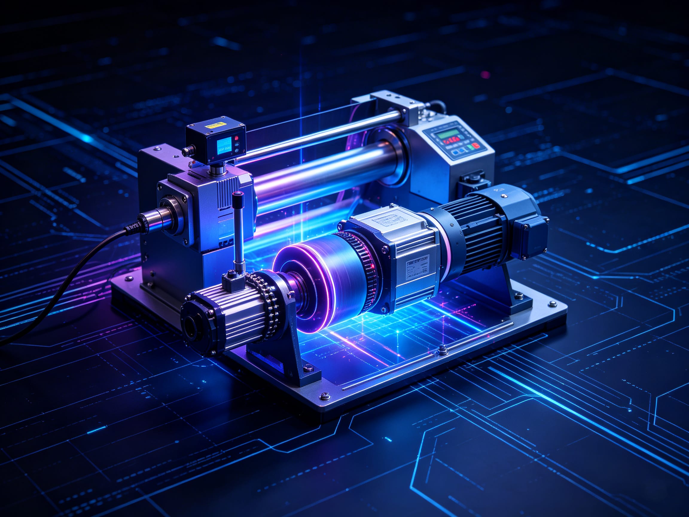
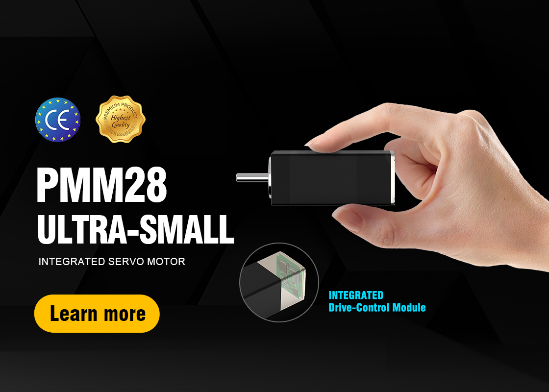
Integrated stepper motor (also known as closed-loop stepper motor system) is a compact, all-in-one motion control solution that merges the motor rotor, high-resolution encoder, and intelligent driver into a single sealed housing. Unlike traditional open-loop stepper motors, which rely on pulse counting without feedback, integrated models use real-time position feedback to eliminate step loss, enhance dynamic response, and deliver servo-like performance at a fraction of the cost and complexity.
1.Introduction: The Evolution of Precision Motion Control
 The integrated stepper motor emerged as a direct response to the limitations of conventional stepper systems — particularly in applications demanding reliability under variable loads, high-speed operation, or space-constrained environments. By embedding feedback and control logic within the motor body, manufacturers have redefined what “step motor” means in modern automation.
Key innovations include:
- Built-in encoder: Typically a 12-bit to 18-bit absolute or incremental magnetic encoder, mounted directly on the shaft.
- Onboard DSP/FPGA controller: Executes advanced algorithms such as Field-Oriented Control (FOC), microstepping interpolation, and adaptive current regulation.
- Multi-protocol communication: Native support for Pulse/Dir, Modbus-RTU, CANopen, EtherCAT, and analog inputs.
- Smart power management: Dynamic current reduction during idle states (“auto-sleep”) to reduce heat and energy consumption.
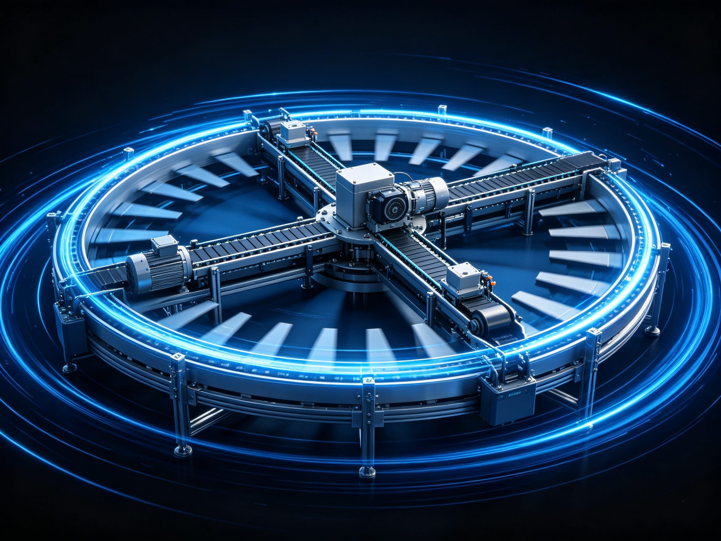
This integration eliminates external driver boxes, reduces wiring by up to 70%, minimizes electromagnetic interference (EMI), and simplifies system design — making it ideal for high-density installations like SMT pick-and-place machines, robotic arms, and medical imaging systems.
“The integrated stepper motor is not just a motor with a driver — it’s a self-contained motion intelligence unit.” — Industrial Automation Review, 2025
2.Core Technical Architecture
| Component | Function | Typical Specification |
| Motor Rotor | Converts electrical energy to mechanical torque | Hybrid stepper, 2-phase, NEMA 17–34 (20–86mm frame) |
| Encoder | Real-time position & velocity feedback | 4096–16384 counts/rev, absolute or incremental, IP67 sealed |
| Driver IC | Current control, microstepping, closed-loop logic | 32-bit DSP, 0.1–5A output, 1/256 microstep resolution |
| Power Input | DC supply for internal electronics | 24VDC ±10%, 10–48VDC wide range models available |
| Communication | Interface with PLC/PC/controller | RS232, CANopen, EtherCAT, Pulse/Dir, Modbus RTU |
| Protection | Safety and durability | Over-current, over-voltage, over-temperature, short-circuit |
3.How Closed-Loop Control Works
Traditional stepper motors operate in open-loop: the controller sends pulses, assuming the rotor follows exactly. If load exceeds torque, the motor misses steps — leading to positioning errors.

In an integrated stepper motor, the process is fundamentally different:
- Command Received: Controller sends target position (e.g., “Move to 1200 steps”).
- Motor Executes: Driver energizes windings to rotate rotor.
- Encoder Feeds Back: Real-time position data (e.g., “Actual: 1185 steps”) is sent to onboard controller.
- Error Correction: Controller calculates deviation (15 steps) and applies corrective current pulse.
- Dynamic Adjustment: Torque output is modulated in real time to compensate for inertia, friction, or load spikes.
- Smooth Trajectory: S-curve acceleration/deceleration profiles are auto-generated to minimize vibration.
This closed-loop feedback loop runs at 10–50 kHz, enabling sub-0.1° positioning accuracy — comparable to low-end servo systems — without the need for complex tuning or expensive encoders.
4.Integrated Stepper Motor vs. Traditional Stepper Motor
| Feature | Integrated Stepper Motor | Traditional Open-Loop Stepper |
| Position Accuracy | ±0.02° (with encoder feedback) | ±0.5–1.0° (prone to step loss) |
| Torque Utilization | Up to 95% of holding torque usable | Typically limited to 60–70% to avoid stall |
| Speed Performance | Up to 3000 RPM (with smooth S-curve) | Max 1000–1500 RPM before resonance |
| Noise & Vibration | 30–50% lower due to adaptive damping | High at mid-range speeds |
| System Complexity | Single unit, 2–3 wires | Motor + driver + encoder + cables (5–10 wires) |
| Installation Time | <15 minutes | 45–90 minutes (wiring, grounding, shielding) |
| Cost (System Level) | Higher unit cost, lower total BOM | Lower unit cost, higher integration cost |
| Maintenance | Self-diagnostic, error logs | Manual fault finding, no telemetry |
| EMI Susceptibility | Low (shielded internal design) | High (external cables act as antennas) |
Integrated models reduce system-level cost by eliminating external drivers, reducing cable harnesses, and cutting commissioning time — often paying for themselves in under 6 months in high-mix production lines.
5.Key Technical Parameters Explained

Step Angle & Resolution
- Standard step angle: 1.8° (200 steps/rev)
- Microstepping support: Up to 1/256 → effective resolution: 51,200 steps/rev
- Enables smooth motion at low speeds, critical for precision dispensing or optical alignment
Torque-Speed Curve
The torque output of an integrated stepper motor declines with speed due to inductance and back-EMF. The curve follows:
T(v)=T0 · (1-V/Vmax)2
where:
- T0 = Holding torque (N·m)
- v = Operating speed (RPM)
- vmax = Maximum speed (typically 1500–3000 RPM)
Example: A motor with 𝑇0=1.2 N \ cdotpm, vmax=2500RPM
At 1000 RPM → T=1.2⋅(1−0.4)2=0.432N\cdotpm
At 2000 RPM → T=1.2⋅(1−0.8)2=0.048N\cdotpm
Inertia Matching
Optimal load-to-rotor inertia ratio: 1:1 to 10:1
Exceeding 15:1 risks instability, even with closed-loop control.
Thermal Management
- Max winding temperature: 130°C
- Built-in thermal sensor triggers current derating at 85°C
- Aluminum housing acts as heat sink — no external fan required in most applications
6.Market Leaders and Product Series
| Brand | Series | Max Torque | Resolution | Communication | Key Applications |
| NiMotion | STM Series | 3.0 N·m | 1/256 | Pulse, Modbus, CANopen | CNC, 3D Printers, Packaging,Medical |
| Leadshine | iEM Series | 3.0 N·m | 1/256 | Pulse/Dir, RS232, CANopen | CNC, 3D Printers, Packaging |
| Nidec | SM-CL Series | 2.5 N·m | 1/128 | EtherCAT, Modbus | SMT, Medical Robotics |
| Omron | ZS-CL Series | 1.8 N·m | 1/256 | CANopen, Pulse/Dir | Semiconductor Handling |
| THK | SPS Series | 1.5 N·m | 1/128 | EtherCAT, Analog | Precision Stages, Lab Automation |
| Copley Controls | AccuDrive | 4.0 N·m | 1/512 | EtherCAT, CANopen | High-Speed Assembly |
| Applied Motion | iStep | 2.8 N·m | 1/256 | Modbus, RS485 | Food & Beverage, Packaging |
Note: All listed products comply with IEC 60034-1, UL 508, and CE EMC directives.
7.Primary Application Domains
| Industry | Use Case | Benefit of Integrated Stepper |
| Electronics Manufacturing | SMT pick-and-place, vision alignment, nozzle positioning | Eliminates vibration-induced misplacement; reduces calibration downtime |
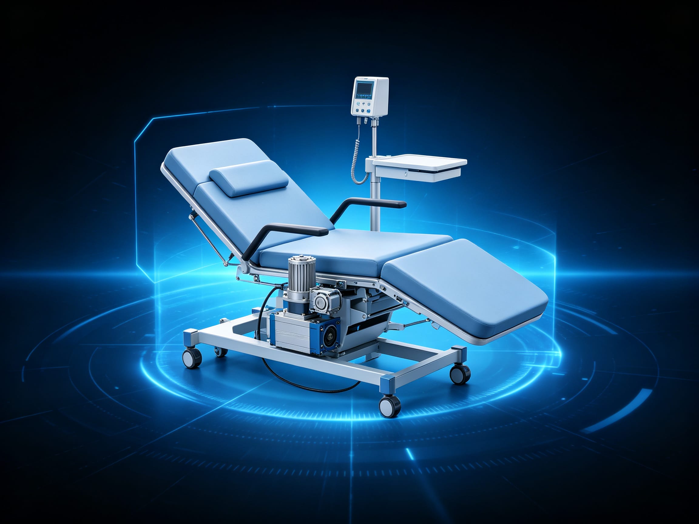
| Medical Devices | Blood analyzer rotor drives, ventilator valve control, endoscope actuators | Silent operation, no EMI interference with sensitive sensors |
| Laboratory Automation | Liquid chromatography injectors, spectrometer grating scanners | Sub-micron repeatability; no feedback wiring near high-voltage components |
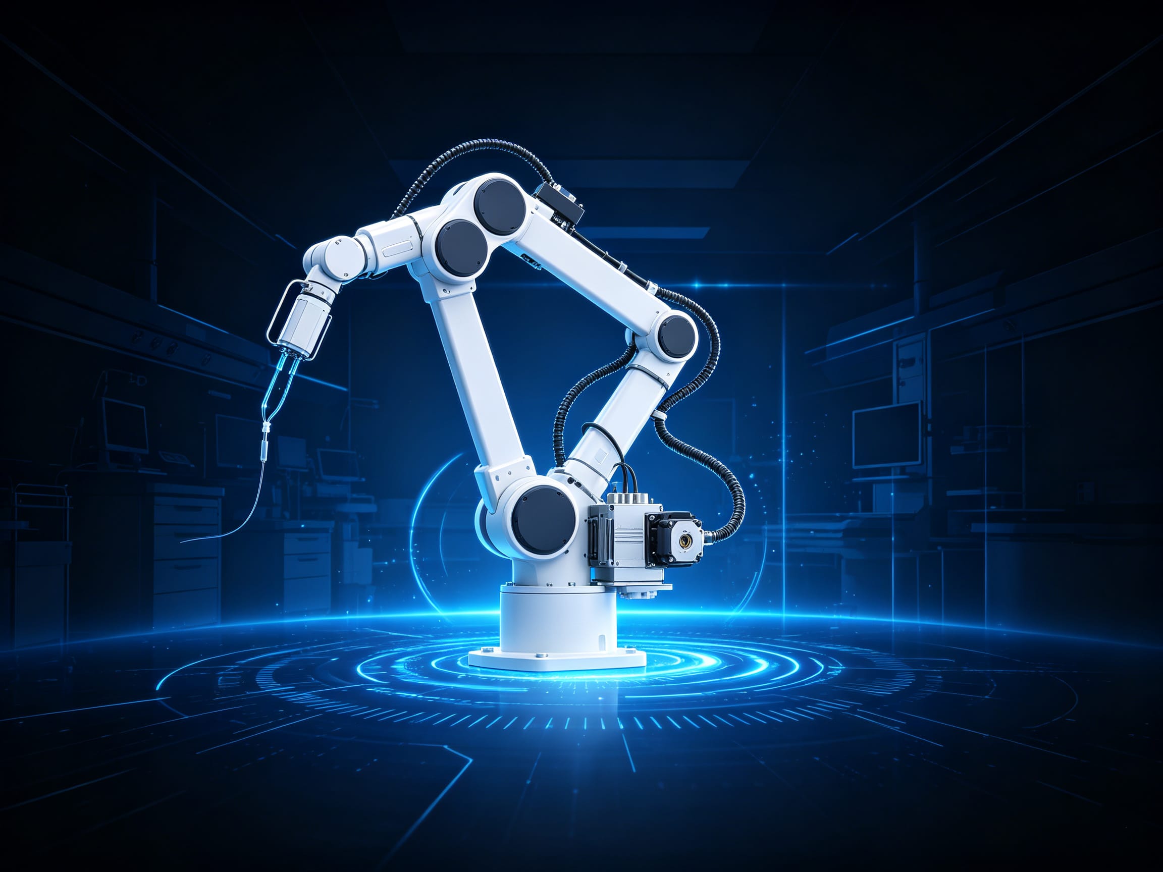
| Robotics | SCARA joint actuators, Delta robot end-effectors | Compact form factor enables lighter arms; integrated diagnostics simplify maintenance |
| Packaging | Label applicators, capping machines, carton fold units | High cycle life (>10 million cycles), IP65 protection against dust and washdown |
| Stage & Entertainment | Moving lights, automated curtains, rigging systems | Smooth motion, zero step loss during rapid direction changes |
8.Installation & Environmental Guidelines
Mounting Requirements
- Use flexible couplings (e.g., bellows or beam couplings) to isolate shaft misalignment
- Torque specification: 0.5–1.0 N·m for mounting screws (do not overtighten)
- Ensure axial and radial runout < 0.05 mm
Heat Dissipation
- Mount on metal chassis with thermal paste interface
- Avoid enclosing in plastic housings without ventilation
- Derate torque by 15% if ambient temperature > 40°C
EMI Protection
- Use shielded twisted-pair cables for power and signal lines
- Ground motor housing at single point only
- Install ferrite cores on input power lines
- Keep motor cables ≥ 30 cm away from high-frequency sources (VFDs, RF transmitters)
Environmental Ratings
| IP Rating | Use Case |
| IP54 | Indoor factory environments |
| IP65 | Washdown areas, food processing |
| IP67 | Outdoor or high-dust environments |
9.Troubleshooting Common Failures
| Symptom | Likely Cause | Solution |
| Motor stalls under load | Load exceeds torque curve; inertia mismatch | Increase torque rating; reduce load inertia; enable torque boost mode |
| Erratic movement / jitter | Encoder signal noise; poor grounding | Check shielded cable integrity; add ferrite beads; verify single-point ground |
| Overheating | Continuous high current; poor heat dissipation | Enable auto-sleep; improve airflow; check for mechanical binding |
| Communication timeout | Baud rate mismatch; cable length > 10m | Verify protocol settings; use RS485 repeater for long runs |
| No response on power-up | Faulty power supply; internal driver failure | Test input voltage; check fuse; contact manufacturer for RMA |
| Position drift after power cycle | Encoder not absolute; no homing | Use absolute encoder model; implement homing routine on startup |
Integrated motors often log error codes via Modbus registers (e.g., 0x1001 = Overcurrent, 0x1002 = Encoder Fault). Use manufacturer software to read diagnostic logs.
10.Industry Standards & Certifications
| Standard | Scope | Compliance Requirement |
| IEC 60034-1 | Rotating electrical machines — General requirements | Thermal class, insulation, vibration limits |
| IEC 60204-1 | Safety of machinery — Electrical equipment | Emergency stop, isolation, grounding |
| UL 508 | Industrial Control Equipment | Overload protection, enclosure integrity |
| CE (EN 61800-3) | EMC for adjustable speed drives | Emissions and immunity limits |
| RoHS 3 | Restriction of hazardous substances | Lead, mercury, cadmium limits |
| REACH | Chemical safety | SVHC compliance for plastics and coatings |
All major brands (Nidec, Omron, Leadshine) provide certified compliance documentation with each product shipment.
11.Trends & Future Outlook
- AI-Powered Predictive Maintenance: Embedded sensors now feed data to edge AI modules that predict bearing wear or insulation degradation based on current waveform anomalies.
- IoT Integration: Motors with built-in MQTT/OPC UA support can connect directly to cloud platforms (e.g., AWS IoT, Azure Digital Twins) for remote monitoring.
- Digital Twin Synchronization: Real-time motor position and torque data mirrored in virtual factory models for simulation and optimization.
- Self-Calibrating Systems: New models auto-detect load inertia and tune PID parameters on startup.
- Energy Harvesting: Experimental prototypes recover braking energy to recharge onboard capacitors.
By 2027, over 60% of new automation systems in Asia-Pacific will adopt integrated stepper motors over traditional servo systems for mid-torque applications, driven by cost, simplicity, and reliability.
12.Selection Checklist: 5-Step Guide
-
1.Determine Required Torque
Calculate peak load torque + 50% safety margin
Select motor with rated torque ≥ 1.5× required -
2.Match Speed & Resolution
Ensure max RPM ≥ application need
Verify microstep resolution supports positioning accuracy (e.g., 0.01° = 36,000 steps/rev) -
3.Verify Communication Protocol
Match controller interface: Pulse/Dir for PLCs, CANopen for industrial networks, EtherCAT for high-speed sync -
4.Assess Environmental Conditions
Choose IP65+ for wet/dusty areas
Confirm operating temperature range (e.g., -20°C to +60°C) -
5.Evaluate Support & Warranty
Prefer vendors offering free configuration software, API documentation, and 2-year warranty
13.Conclusion: Why Integrated Stepper Motors Are the New Standard
The integrated stepper motor represents a paradigm shift in motion control: it merges the simplicity of stepper technology with the reliability of servo systems. By eliminating external components, reducing wiring complexity, and adding intelligent feedback, it delivers higher precision, lower total cost of ownership, and faster deployment — especially in small- to mid-scale automation.
For engineers designing systems in electronics, medical, robotics, or packaging industries, choosing an integrated stepper motor is no longer a premium option — it is the smart, future-proof default.
As AI, IoT, and edge computing continue to penetrate industrial automation, the integrated stepper motor will evolve from a “smart motor” into a self-aware actuator node — capable of diagnosing, adapting, and communicating — making it the cornerstone of next-generation smart factories.