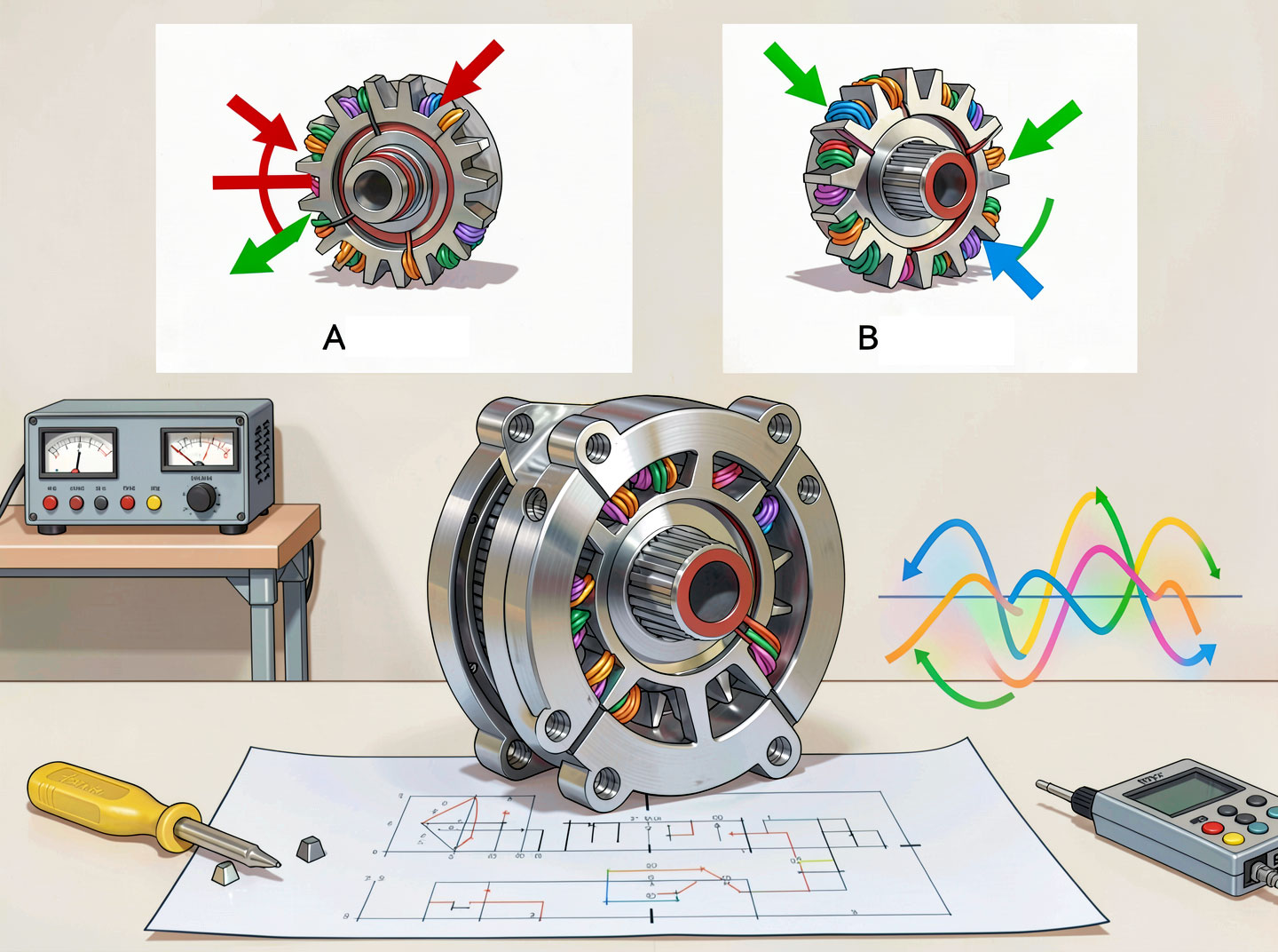
Hybrid stepper motor working principle
Introduction

The hybrid stepper motor working principle is a fascinating blend of electromagnetism and mechanical design. Unlike a simple DC motor that rotates continuously, a stepper motor moves in precise angular increments (steps). The hybrid stepper motor achieves these steps by alternately energizing stator windings to create magnetic fields that interact with a specially designed toothed rotor containing a permanent magnet.
This article explains step‑by‑step how a hybrid stepper motor operates, from basic magnetic principles to the detailed stepping sequence. We also cover key concepts like step angle, detent torque, and microstepping.
Fundamental Principle: Magnetic Reluctance + Permanent Magnet Flux
Two magnetic phenomena work together in a hybrid stepper motor:
Permanent magnet flux – The axially magnetized permanent magnet in the rotor creates a fixed magnetic field. One rotor cup becomes north‑polarized, the other south.
Reluctance torque – When stator teeth are energized, the magnetic circuit prefers the path of least reluctance (minimum air gap). The rotor teeth align with stator teeth to minimize the air gap.
By energizing different stator phases, the stator magnetic field rotates, pulling the rotor with it. Because the rotor teeth are offset between the two cups, the motor can achieve half‑step increments, doubling resolution.
Step‑by‑Step Working Sequence (Two‑Phase, 1.8° Hybrid Stepper Motor)

Let’s use a common 2‑phase hybrid stepper motor with 50 rotor teeth and 8 stator poles. The step angle is 1.8° (200 steps/rev). The rotor has two cups – Cup A and Cup B – each with 50 teeth, but offset by half a tooth pitch (3.6° mechanical).
Phase 1: Energize Phase A+ (Current flows one way in Phase A winding)
Stator poles of Phase A are magnetized, creating south poles on some teeth and north on others.
Rotor Cup A (say north‑polarized) aligns its teeth with the stator south poles to minimize air gap.
Rotor Cup B (south‑polarized) aligns its teeth with stator north poles.
Result: Rotor locks into a stable position.
Phase 2: De‑energize Phase A, energize Phase B+
Stator magnetic field shifts by 1.8° electrical.
The rotor teeth of Cup A now are slightly misaligned with previous stator poles.
The reluctance torque pulls the rotor to the new equilibrium where Cup A teeth align with the newly energized Phase B poles.
Rotor rotates exactly 1.8° mechanical.
Phase 3: Energize Phase A with opposite polarity (A‑)
Phase A current reverses. Stator poles switch magnetic polarity.
Because the two rotor cups have opposite permanent magnet polarities, the rotor advances another 1.8°.
Phase 4: Energize Phase B with opposite polarity (B‑)
Final step of the sequence. After this, the pattern repeats.
Important: The offset between the two rotor cups (half tooth pitch) allows the motor to take half steps if the phase current sequence is modified (wave drive or half‑step drive).
Role of Rotor Teeth and Stator Teeth
A hybrid stepper motor relies on the number of teeth to determine the step angle:
Rotor teeth number (N_r) – Typically 50 for a 1.8° motor, 100 for a 0.9° motor.
Stator poles – Usually 8, each with multiple teeth (e.g., 5 teeth per pole for a total of 40 stator teeth).
The alignment occurs between rotor teeth and stator teeth. Because the teeth are small, the rotor moves in very fine increments. This is why a hybrid stepper motor achieves high precision without a gearbox.
Magnetic Circuit Analysis

Consider a cross‑section of a hybrid stepper motor:
The permanent magnet creates flux that flows axially through one rotor cup, radially across the air gap, through the stator, then axially through the other cup, and back.
Stator windings superimpose additional flux. When a phase is energized, the total flux in some teeth increases (aiding the permanent magnet flux) and decreases in others (opposing).
This creates a net torque that aligns the rotor to minimize the magnetic energy in the system.
Key equation (simplified):
Torque 𝑇∝Φ𝑃𝑀⋅Φ𝑤𝑖𝑛𝑑𝑖𝑛𝑔⋅sin(𝜃𝑒)T∝ΦPM⋅Φwinding⋅sin(θe)
where 𝜃𝑒θe is the electrical angle error between stator and rotor fields.
Step Modes: How a Hybrid Stepper Motor Moves
A hybrid stepper motor can be driven in several modes:
ModeSteps per revolution (1.8° motor)TorqueSmoothnessFull step (2‑phase on)200HighModerateHalf step400MediumBetterMicrostepping (e.g., 1/16)3200LowerVery smooth
In full step (two phases energized simultaneously), the rotor aligns to a position between two adjacent full‑step positions of single‑phase energization, increasing holding torque by about 40% compared to wave drive.
In microstepping, the phase currents are sinusoidally modulated, allowing the rotor to stop at any intermediate position. This is a major advantage of the hybrid stepper motor over other stepper motor types.
Detent Torque in Hybrid Stepper Motors
Detent (cogging) torque occurs even when the motor is unpowered due to the permanent magnet interacting with stator teeth. In a hybrid stepper motor, detent torque is typically 5–10% of holding torque – much lower than in permanent magnet stepper motors. This low detent torque allows smooth starting and stopping.
Practical Example: Energizing Sequence Table
For a 2‑phase hybrid stepper motor (Phase A and Phase B), a full‑step sequence with both phases always on (most common) is:
StepPhase A currentPhase B currentRotor position (electrical)0+I+I0°1+I-I45°2-I-I90°3-I+I135°4+I+I180° (same as step 0 mechanically shifted by 1.8°)
Each electrical cycle corresponds to 4 full steps = 7.2° mechanical rotation for a 1.8° motor (since 7.2° / 1.8° = 4 steps per electrical cycle).
Common Misconceptions
“A hybrid stepper motor is just a permanent magnet motor with teeth.”
– False. The axial magnet and two‑cup rotor are unique to hybrids.“Hybrid stepper motors cannot run at high speeds.”
– They can reach 2000–3000 RPM with proper drivers, but torque decreases. For very high speed, servo motors are better.“The working principle is identical to a VR stepper motor.”
– No, VR has no magnet and thus no holding torque when unpowered. The hybrid uses both magnet and reluctance.
Conclusion
The hybrid stepper motor working principle elegantly combines permanent magnet flux and variable reluctance to achieve precise, repeatable steps. By energizing stator phases in sequence, the stator magnetic field rotates and drags the toothed rotor along. The unique dual‑cup rotor with an axial magnet allows very fine step angles (0.9°–1.8°), making the hybrid stepper motor the backbone of modern motion control.