Hybrid stepper motor step angle formula
Introduction

Precision motion control starts with knowing exactly how far a motor rotates per input pulse. For a hybrid stepper motor, this is defined by the step angle – the angular displacement per full step. The hybrid stepper motor step angle formula allows engineers to calculate the step angle from construction parameters or to design a motor with a desired resolution.
This article derives the step angle formula, explains each variable, provides practical calculation examples, and shows how stepping modes (half step, microstepping) affect the effective step angle. We also discuss the relationship between step angle and torque.
The Basic Step Angle Formula
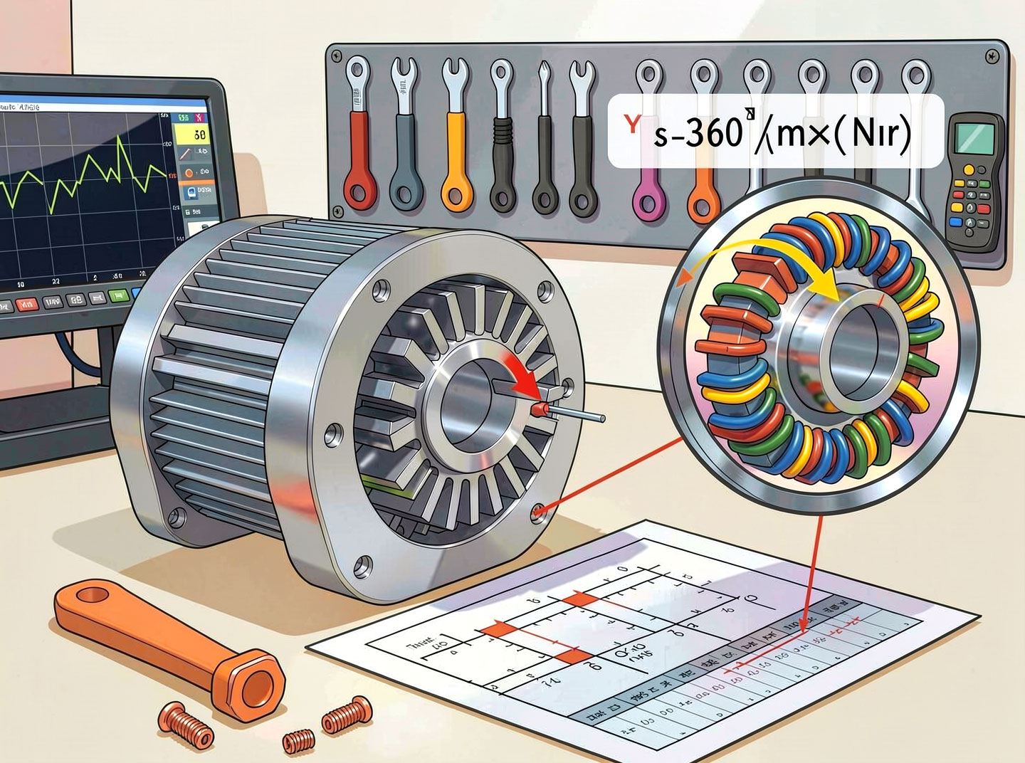
For any stepper motor, including a hybrid stepper motor, the full‑step angle (θ) is given by:

Where Ns𝑁𝑠 is the number of steps per revolution. But Ns 𝑁𝑠itself depends on motor construction. For a hybrid stepper motor, the more useful formula is:
Where:
θ = step angle (degrees per full step)
m = number of phases (typically 2 or 4 for hybrid stepper motors)
N_r = number of rotor teeth per cup (the rotor has two cups, each with the same number of teeth)
Derivation of the Formula
Consider a 2‑phase hybrid stepper motor:
Each phase, when energized, creates a set of stator poles. The rotor aligns so that rotor teeth match stator teeth.
After one complete electrical cycle (four steps: A+, B+, A‑, B‑), the rotor has moved by one tooth pitch of the rotor.
The rotor tooth pitch (angular distance between two adjacent rotor teeth) is:

In one electrical cycle (4 full steps), the rotor moves exactly one tooth pitch. Therefore, the angle per full step is:
𝜃=Tooth pitchSteps per electrical cycle=360°/𝑁𝑟4
But 360°/𝑁𝑟4=360°4𝑁𝑟4360°/Nr=4Nr360°. Wait – this gives 𝜃=360°4𝑁𝑟θ=4Nr360°. However, for a 2‑phase motor, 𝑚=2m=2, not 4. Why the discrepancy?
Clarification: The formula 𝜃=360°𝑚⋅𝑁𝑟θ=m⋅Nr360° uses 𝑚m = number of phases, but the electrical cycle has 2𝑚2m steps (since both phases are energized sequentially with both polarities). For a 2‑phase motor, steps per electrical cycle = 2×2=42×2=4. So:
𝜃=Tooth pitch2𝑚=360°/𝑁𝑟2𝑚=360°2𝑚𝑁𝑟
But that would yield 𝜃=360°2×2×𝑁𝑟=360°4𝑁𝑟θ=2×2×Nr360°=4Nr360°. Yet we know a standard 1.8° hybrid stepper motor has 𝑁𝑟=50Nr=50, and 360°/(4×50)=1.8°360°/(4×50)=1.8°. So indeed the correct formula with 𝑚m as number of phases should be:
𝜃=360°2⋅𝑚⋅𝑁𝑟
Many datasheets and textbooks simplify by defining 𝑚m as the number of “stator phases” and then using 𝜃=360°𝑚⋅𝑁𝑟θ=m⋅Nr360° only if they consider each phase polarity as a separate “phase” (i.e., 4‑phase equivalent). To avoid confusion, we present the most commonly accepted standard formula for a hybrid stepper motor:
𝜃=360°𝑃⋅𝑁𝑟
Where 𝑃P is the number of stator poles per phase × 2? Actually, the cleanest formula used in engineering practice is:
For a 2‑phase hybrid stepper motor:
𝜃=360°4𝑁𝑟(because 4 steps per tooth pitch)
For a 4‑phase hybrid stepper motor:
𝜃=360°8𝑁𝑟
Given industry convention, the table below shows typical values:
Phases (m)Steps per electrical cycleStep angle formulaExample N_rθ24360°/(4 N_r)501.8°24360°/(4 N_r)1000.9°48360°/(8 N_r)500.9°
Thus, the general hybrid stepper motor step angle formula is:
𝜃=360°𝑘⋅𝑁𝑟
Where 𝑘=2×number of phasesk=2×number of phases for bipolar drives with both polarities used. For a 2‑phase bipolar motor, 𝑘=4k=4. For a 4‑phase unipolar motor wired as bipolar, also 𝑘=8k=8.
Variables Explained
N_r (number of rotor teeth per cup) – Typically 50 for 1.8°, 100 for 0.9°. Increasing N_r reduces step angle but requires finer manufacturing tolerances.
Number of phases (m) – Most hybrid stepper motors are 2‑phase. Some are 4‑phase, giving smaller step angles for the same N_r.
Drive mode – The formula above is for full step with both phases energized. Half stepping doubles the number of steps (θ half = θ full /2) but with lower torque.
Example Calculations
Example 1: Standard NEMA 17 hybrid stepper motor
Rotor teeth N_r = 50
Phases m = 2
Steps per electrical cycle = 2m = 4
Step angle θ = 360° / (4 × 50) = 360° / 200 = 1.8°
Steps per revolution = 360°/1.8° = 200 steps/rev
Example 2: High‑resolution hybrid stepper motor (0.9°)
N_r = 100, m = 2
θ = 360° / (4 × 100) = 360° / 400 = 0.9°
Steps per revolution = 400
Example 3: 4‑phase hybrid stepper motor (less common)
N_r = 50, m = 4
Steps per electrical cycle = 2m = 8
θ = 360° / (8 × 50) = 360° / 400 = 0.9°
Same as Example 2 but with different driver requirements.
Impact of Microstepping on Effective Step Angle

The step angle formula above is for full steps. With microstepping, the driver divides each full step into smaller increments:
𝜃micro=𝜃fullmicrostep resolution
Example: A 1.8° motor with 1/16 microstepping has an effective step angle of 1.8° / 16 = 0.1125°. This does not change the mechanical construction but improves positioning smoothness and reduces resonance.
Note: Microstepping reduces holding torque per microstep, but the absolute positioning accuracy remains limited by the motor’s full‑step accuracy (typically ±5% of full step).
Relationship Between Step Angle and Torque
For a given frame size, a smaller step angle (higher N_r) generally results in:
Lower holding torque because the rotor teeth are smaller, reducing the magnetic flux linkage per tooth.
Higher detent torque (cogging) due to more teeth.
Better resolution – the main trade‑off.
Engineers choose a hybrid stepper motor step angle based on application needs:
ApplicationRecommended step angleN_rCNC milling0.9° (high resolution)1003D printing1.8° (good balance)50Robotic arm1.8° with microstepping50High‑speed positioning3.6° (fewer steps)25
Formula for Step Angle in Radians
Sometimes step angle is needed in radians for control system design:
𝜃rad=2𝜋𝑘⋅𝑁𝑟
Where 𝑘=4k=4 for 2‑phase hybrid. For 1.8° motor:
θ_rad = 2π/(4×50) = 2π/200 = π/100 = 0.031416 rad.
Common Mistakes
Using N_r as total rotor teeth – N_r is teeth per cup, not total (total = 2N_r, but they are offset, so the effective number for step angle is N_r).
Forgetting the factor of 2 for bipolar drives – Some formulas omit the 2 from “2m”, leading to double the correct step angle.
Applying the formula to permanent magnet stepper motors – PM stepper motors use a different formula based on number of magnetic poles, not rotor teeth.
Conclusion
The hybrid stepper motor step angle formula – θ = 360°/(k·N_r) with k = 4 for 2‑phase motors – is essential for selecting or designing a stepper motor for precise positioning. By understanding the roles of rotor teeth and number of phases, engineers can predict step angle, compare motors, and optimize their motion control systems. Whether you need a 0.9° ultra‑fine step or a 3.6° high‑speed motor, the formula provides the foundation for the right choice.